


Feeder Table
KomTec-Assembly Table GM (Feeder Table)

KomTec-Assembly Table GM (Feeder Table)
The variable assembly station for universal use in the assembly of wall, gable, roof and ceiling elements paneled on one or two sides as well as knee sticks in frame construction.
Heavy basic structure of the machine frame for an absolutely flat work surface.
The assembly station on which the frame work and the beam layer can be laid out, clamped and nailed at the exact angle.
- The width adjustment and the pressing of the elements takes place motorized at the push of a button.
- The framework is positioned via a movable pressure beam using motor-driven precision threaded spindles.
- Subdivided press beam for the simultaneous processing of 2 wall elements of different heights.
- The pressing pressure can be continuously adjusted using an overcurrent relay.
- The spindle drive ensures that the wall elements are pressed absolutely parallel, even if several small wall elements are being produced at the station at the same time.
- As far as is technically possible, the stations are covered over the entire surface for the laying out of individual frame constructions.
- The working height of the stations is 700 mm.
- The heavy mechanical engineering is the basis for absolutely flat elements with an element weight of up to 4.0 t.
- The stations are delivered completely finished and functional. All that is required to set up the systems is a level, load-bearing floor and electrical and compressed air connections
- System grid beams with locking pins installed transversely in the work surface of the station, for inserting the locking pins, for pressing wall elements and knee sticks with a height of less than 2.40 m and press cylinders for sloping wall constructions.
- Stop at the bottom and on the left with 38 plug-in reversible bolts in rust-free design Distance between the mounts for the stop bolts, approx. 600 mm
- Installation device up to 80°(95°) inclination angle
- Front end of station 2 electrical and compressed air connections for connecting hand-held devices
- The stations are built on a modular principle so that they can be supplemented with a receiving station to form a complete turning station either immediately or later.
Workspace
Working surface length (element width): from min. 1,000 - max. 12,000 mm
Work surface width (element height): from min. 595 - max. 3,500 mm
Adjustment range of the pressure bar: from min. 2,400 - max. 3,500 mm
Stop height (element thickness): up to 150 mm
Working height/table height: 700 mm
================================================== =======
If a receiver table is used later, the 350 mm stop height is problematic.
Additional Equipment for Installation in an Assembly Table (Feeder Table)
Presscylinder

for insertion into the perforated rails, including permanently mounted compressed air line and switch. Stroke 125 mm, pressing pressure at 6 bar approx. 1680 N
Lochblechplatte Typ. GL

for universal use of press cylinders and counter bearings.
Holes of 17 mm, thickness of 4 mm, hole pattern 65 mm.
Folienabwickelstation
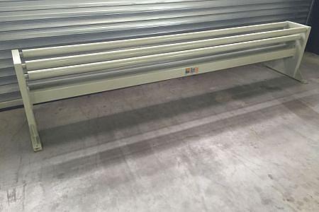
with 5 large-sized bearing rollers with ball bearings on both sides, without cutting device, for film widths up to 3,500 mm External dimensions/setup dimensions:
Length 600mm
Width 3,600mm
Height 770mm
Integrated ceiling clamping device for the assembly table (transmitter station)
The integrated roof and ceiling clamping device enables rafters or ceiling beams to be positioned precisely.
In order to use the assembly table again later for the production of wall elements, only the socket bolts have to be removed, the clamping elements can always remain assembled and positioned.
Roof and ceiling elements are not suitable for turning.
Tensioning elements for roof and ceiling tensioning station.
Pneumatic for roof + ceiling clamping unit for clamping using locking pins.
One clamping element is mounted in the press beam, the others are integrated into the assembly table.
The rafter width can be adjusted from 60 - 220 mm using the tape measure.
The clamping element is suitable for turning operation, only the locking pins have to be removed.
With 4 clamping elements per clamping axis, we recommend 12 clamping elements.